
Injection Moulding Terminology Explained: A Glossary for Product Buyers
If you have ever received a technical drawing full of terms like draft angle, gate and shot weight, or nodded along in a meeting without really knowing what a T1 sample is, this glossary is for you.
At Great Central Plastics, we have been running injection moulding, toolmaking and finishing operations from our Northamptonshire base since 1998. This glossary brings together the terms we use every day on the shop floor, in DFM reviews, and in conversations with the product buyers, designers and project managers we work with. It is written in plain English, without the assumed knowledge, so you can spot potential issues at the design stage, review quotes and drawings with more confidence, and get more from your first conversation with a moulder.
The terms are grouped by topic, so you can either read the section that matters most for your project or use the quick reference index below to jump to a specific term.
Quick reference index
The moulding process: Injection moulding, cycle time, shot, shot weight, clamping force, tonnage, kiloNewtons calculations, cooling time, ejection
Tools and tooling: Mould tool, cavity, core, core pull, gate, multi-cavity tool, family tool, tool life, tool class, hot runner, cold runner, tool trial
Part features and design: Draft angle, wall thickness, rib, boss, undercut, parting line, runner, sprue, vent, cavitation
Materials and processing: Thermoplastic, resin, masterbatch, regrind, purging, shrinkage, injection pressure
Defects and quality: Sink mark, warp, flash, short shot, weld line, burn mark, flow line
Design and production stages: DFM, T1 samples, first off, approval sample, production run, ISIR / PPAP
Finishing and post-moulding: Post-moulding, overmoulding, insert moulding, in-mould labelling, chrome plating, hot foil, resin doming, ultrasonic welding
The moulding process
Injection moulding. The process of forming plastic parts by heating a thermoplastic material until it flows, injecting it into a closed mould tool under pressure, and cooling it until it solidifies into the shape of the tool cavity. It is used to produce anything from small components to large, complex parts in high volumes. Our own moulding capabilities span a wide range of machines and materials, from bespoke industrial parts to high-volume promotional products. For a fuller overview, see our guide to thermoplastics for injection moulding.
Cycle time. The time it takes to complete one full moulding cycle, from the mould closing to the finished part being ejected and the mould closing again, ready for the next cycle. Cycle time governs how many products you can produce per hour, and is a key driver of production capacity, affecting the overall cost and efficiency of a project.
Shot. A single injection of molten plastic into the mould tool, used in one moulding cycle. Each shot produces one set of parts, which may be a single part or several depending on the tool.
Shot weight. The total weight of plastic delivered in one shot, including the parts themselves and any runner or sprue material. Shot weight is used to size moulding machines and calculate material usage.
Clamping force. The mechanical force applied to keep the two halves of the mould tool closed while plastic is injected under pressure, during the injection moulding cycle. It is measured in tonnes, typically starting at around 5 to 10 tonnes in very small machines, between 50 and 500 tonnes for most typical applications and up to 2000 to 4000 tonnes for the largest applications.
Tonnage. The clamping force rating of an injection moulding machine, expressed in metric tonnes. A 200-tonne machine can apply a maximum 200 tonnes of clamping force. Larger parts and higher injection pressures need higher tonnages.
KiloNewtons (kN) calculations. The unit of measurement used by machinery manufacturers to measure clamping force. While often informally expressed in tonnes, kilonewtons are the standard scientific unit used on technical datasheets. One metric tonne of force is equal to exactly 9.81 kiloNewtons. On the production floor, engineers frequently use a simplified rule of thumb where one metric tonne equates to 10 kiloNewtons for fast mental calculations. For example, a 250 tonne machine is precisely 2452.5 kN, or roughly 2500 kN using the approximate calculation.
Cooling time. The time the plastic spends solidifying in the mould before the part can be safely ejected without deformation. Cooling is often the longest part of the cycle and depends on wall thickness, material and tool design. Optimisation of cooling time is therefore a vital component of an efficient moulding process.
Ejection. The stage at which the finished part is pushed out of the mould, usually by ejector pins that press against the part as the mould opens, prising it out of the cavity. Alternatively, parts can be removed by robotics and automation or by hand by an operator, depending on volume and cycle time.
Tools and tooling
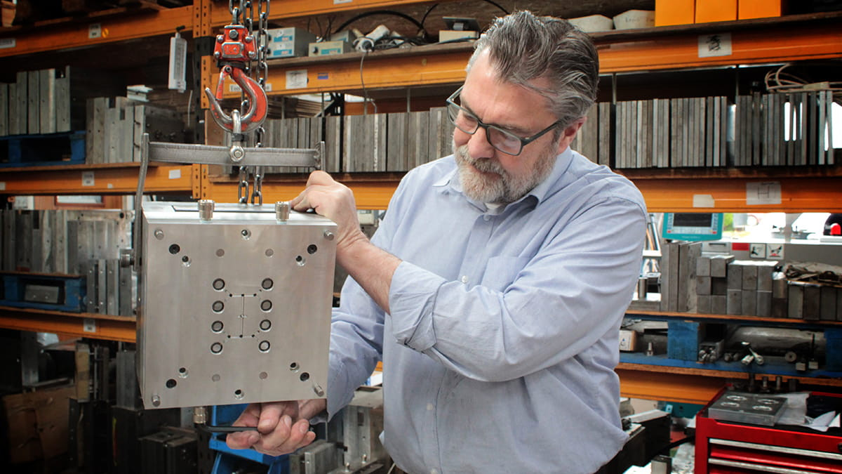
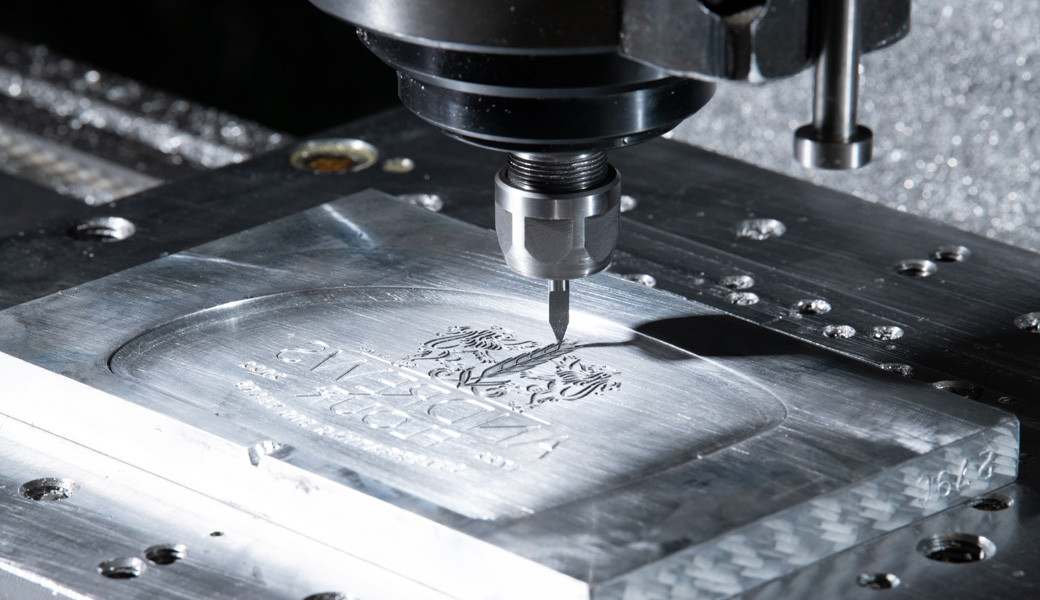
Mould tool. The precision-engineered metal tool, usually machined from steel for high volume, or aluminium for low volume or prototyping applications. The mould tool is used to shape the moulded part during the injection moulding process. Mould tools are made from two halves that come together to form one or more cavities, with the size, shape and surface finish of the cavity exactly determining the dimensions of the finished product. We design and manufacture tools in-house at our Northamptonshire facility, which gives us control over quality and lead times. Read more about our tool room.
Cavity. The hollow space inside the mould tool that gives the moulded part its external geometry, size, and finish. A single-cavity tool produces one part per shot, and a multi-cavity tool produces several. Sometimes called the female half of the mould tool, it is typically attached to the fixed machine platen, directly connected to the injection unit receiving the molten plastic.
Core. The part of the mould that forms the internal geometry and hollow spaces of the plastic part. The cavity forms the outside, the core forms the inside, and together they define the finished part. Sometimes called the male half of a mould tool, it typically resides on the moving platen of the moulding machine, and ejects the finished component as the mould opens.
Core pull. A specialised mechanical or hydraulic mechanism within an injection mould tool that enables core movement. By inserting the core into the moulding area before injection, and retracting before ejection, the tool is able to create complex part features such as sideways holes, internal threads or undercuts.
Gate. The narrow opening in a mould tool through which molten plastic flows into the cavity. The gate is a critical engineering aspect of the tool, precisely controlling the volume, velocity and pressure of the entering material, ensuring the cavity fills uniformly. Once the cavity is full, the gate solidifies, sealing the entrance to the tool and preventing backblow of plastic material. Different types of gate such as direct gates, edge gates, pin point gates and valve gates serve different functions depending on the mould geometry and polymer properties.
Multi-cavity tool. A mould tool with more than one identical cavity, allowing several copies of the same part to be produced in each shot. Multi-cavity tools improve output for high-volume products, allowing the moulding of multiple products per moulding cycle.
Family tool. A mould tool with several different cavities that produce related but non-identical parts in each shot, such as the top and bottom halves of a plastic housing. This approach guarantees that all parts experience identical material batches and processing conditions for perfect colour matching, while reducing upfront tooling investment.
Tool life. The number of shots a mould tool is expected to produce before it needs significant refurbishment or replacement. Tool life depends on the tool material, the properties of the plastic being moulded and how well the tool is maintained. The gold standard for tool life is a hardened steel mould tool, typically delivering a tool life between 1,000,000 and over 5,000,000 cycles, under proper maintenance. An aluminium tool designed for prototyping and lower volume production is much cheaper to manufacture, but has much less longevity, typically having a tool life between 10,000 and 100,000 cycles.
Tool class. A standardised grading system that indicates how long a tool is designed to last. A class 101 tool represents the highest grade of production tooling, engineered to handle volumes over 1,000,000. A class 102 tool is designed for medium-to-high volume production, between 500,000 and 1,000,000 cycles. Class 103 is the standard for medium volume, between 100,000 and 500,000 cycles, typically using pre-hardened tool steels. Class 104 is a low-volume production mould designed to yield under 100,000 cycles, using lower cost materials like mild steel or aluminium. Class 105 is a prototype-only mould, engineered for short-term testing or visual verification, generally under 500 cycles.
Hot runner. A heated system inside the mould tool that maintains the molten plastic at a constant, controlled temperature as it flows to the cavities. Hot runners prevent plastic inside feeding channels from cooling and solidifying between cycles. Hot runners reduce material waste because there is no cooled runner or sprue to remove from each shot. Hot runners are most commonly used in high-speed automated production, where minimising waste and optimising cycle time are critical.
Cold runner. A non-heated channel inside the mould tool that carries plastic to the cavities and solidifies with each shot. Cold runners are simpler and cheaper to build and maintain than hot runners, but they produce scrap runner material that has to be trimmed and reground.
Tool trial. A controlled testing procedure executed on an injection moulding machine to evaluate the performance of a newly manufactured mould before approval for full-scale production. A T0 trial represents a mould tool's very first functional test, checking critical mechanical functions before fine tuning. A T1 trial more closely evaluates the moulded components produced, evaluating and optimising for volumetric shrinkage, warp and aesthetic defects. T2 trials run an optimised moulding process checking specified engineering tolerances and verifying any corrections, and a T3 trial represents the final validation run of a mould tool before mass production, typically carried out in the final production facility, rather than the toolmaker's shop or injection moulding machine factory.
Part features and design
Draft angle. A slight taper added to the vertical walls of a part so it can be released cleanly from the mould. Without draft angles, parts stick in the tool and can be damaged during ejection.
Wall thickness. The thickness of the plastic walls that make up the part. Keeping wall thickness consistent across a part is one of the most important principles in moulding design, because uneven walls lead to warping, sink marks and slower cycle times.
Rib. A thin projecting feature added to a part to increase stiffness without adding excessive wall thickness.
Boss. A raised cylindrical feature, often with a hole through it, used for screws, pins or assembly points.
Undercut. A feature that prevents a part from being released straight out of the mould in the normal opening direction. Undercuts require more complex tooling to handle, such as side actions or lifters, and add to tool cost.
Parting line. The line where the two halves of the mould tool meet. It is often visible as a faint seam on the finished part.
Runner. The channel inside the mould that carries molten plastic from the sprue to the gate. In cold runner tools, the runner material solidifies with each shot and is trimmed off.
Sprue. The main channel through which plastic first enters the mould tool from the injection machine, feeding the runners.
Vent. A tiny channel in the mould that allows air to escape as plastic fills the cavity. Poor venting can cause short shots, burn marks and other defects.
Cavitation. The number of cavities in a mould tool. A four-cavity tool is described as having a cavitation of four. Higher cavitation increases output per shot but adds to tool cost.
Discuss your project with an experienced moulder
Not sure whether your part design is ready for tooling, or which material and process is right for your product? Our team is happy to review your drawings and give honest, practical feedback before you commit to a tool. Get in touch for a no-obligation conversation.
Materials and processing
Thermoplastic. A type of plastic that softens when heated and hardens when cooled, allowing it to be moulded, remoulded and recycled. All standard injection moulding uses thermoplastics. We mould a wide range of thermoplastics in-house, from commodity materials to engineering-grade polymers. Explore our full range of thermoplastic materials.
Resin. The raw plastic material, usually supplied as small pellets, that is melted and injected into the mould. Different resins have very different properties, so choosing the right one is critical. See our material selection guide for more.
Masterbatch. A concentrated pellet of colour or additive that is mixed with the base resin to give the finished part its colour or specific properties, such as UV resistance. For more detail, see our post on masterbatch for injection moulding.
Regrind. Plastic that has been reground into pellets for reuse, either from runners, sprues or rejected parts. We operate an in-house regrind facility, which reduces material waste and cost for suitable projects.
Purging. The process of cleaning residual plastic out of a moulding machine when changing materials or colours, usually with a specialist purging compound. See our post on what a purging agent is for more.
Shrinkage. The amount a plastic part reduces in size as it cools from moulding temperature to room temperature. Every material has a typical shrinkage rate, and toolmakers factor this in when designing the cavity so that the finished part comes out the right size.
Injection pressure. The pressure applied to push molten plastic into the cavity. Too little pressure causes short shots and incomplete parts, too much can cause flash or damage the tool.
Defects and quality
Sink mark. A small dip or depression on the surface of a part, usually over a thick section such as a rib or boss, caused by uneven cooling.
Warp. A distortion of the part shape caused by uneven cooling or internal stresses, resulting in a part that no longer sits flat or true.
Flash. Thin excess plastic that escapes from the cavity along the parting line, usually caused by insufficient clamping force or a worn tool. Flash is trimmed off during finishing.
Short shot. A part that has not filled completely, leaving missing features or thin sections. Short shots can be caused by low injection pressure, cold material or blocked vents.
Weld line. A visible line on the part surface where two flow fronts of molten plastic meet as the cavity fills. Weld lines can be a cosmetic issue and, in some materials, a mechanical weak point.
Burn mark. A darkened area on the part surface, usually caused by trapped air that overheats as it is compressed by the incoming plastic.
Flow line. A wavy pattern on the part surface caused by uneven flow of the material as it fills the cavity. Flow lines are usually cosmetic rather than structural.
Design and production stages
DFM. Short for Design for Manufacturability. A review process in which the part design is checked against moulding best practice before the tool is cut, covering things like draft angles, wall thickness, gate location and undercuts. We include DFM review as part of our standard product development process, because it is the single most effective way to catch expensive problems early. Read more about the importance of DFM in injection moulding.
T1 samples. The first parts produced from a new mould tool, often referred to as "T1" or "tool one" samples. They are used to check that the tool is producing parts to specification before further refinement.
First off. The first acceptable part from a production run, kept as a reference against which the rest of the run is measured.
Approval sample. A part sample submitted to the customer for formal sign-off before full production begins.
Production run. A batch of parts produced to fulfil an order once tooling and samples have been approved.
ISIR / PPAP. Two related terms used in production part approval. ISIR stands for Initial Sample Inspection Report and PPAP stands for Production Part Approval Process. Both are formal documentation packages, particularly common in automotive and regulated industries, that confirm parts meet the required specification before production is approved.
Finishing and post-moulding
Post-moulding. Any process applied to a moulded part after it comes out of the tool, such as trimming, printing, painting, foiling, assembly or packaging. Our in-house post-moulding services mean you can source finished, packaged products from a single supplier.
Overmoulding. A process in which one plastic is moulded over another, typically to add a soft-touch grip or a second colour to a rigid part.
Insert moulding. A process in which a component, often a metal insert such as a threaded fitting, is placed into the mould before plastic is injected around it, becoming embedded in the finished part. For a fuller comparison with overmoulding, see our post on insert moulding vs over moulding.
In-mould labelling. A process in which a pre-printed label is placed in the mould before injection, so the label becomes fused to the surface of the part as it is moulded. Widely used for branded cups and food packaging. Read our complete guide to in-mould labelling.
Chrome plating. A metallic finishing process applied to certain plastic parts, most notably ABS, to give them a bright, durable chrome appearance. Common on automotive badges and decorative parts, and one of our specialisms. Read more about our chrome plating capabilities.
Hot foil. A finishing process that applies a thin metallic or coloured foil to a moulded part using heat and pressure, used to add logos, text or decorative details. See our hot tip foiling page for more.
Resin doming. A finishing process that applies a clear resin coating over a printed or moulded surface, creating a raised, glossy, three-dimensional appearance. Widely used for badges and decals. Explore our resin decals capabilities.
Ultrasonic welding. A process that uses high-frequency vibrations to fuse two plastic parts together at their contact surfaces, without adhesives or fasteners. For more detail, see our post on ultrasonic welding explained.
Talk to Great Central Plastics about your next project
Understanding the terminology makes it much easier to have a productive first conversation with a moulder, but the real value comes from a team that can apply that expertise to your specific product.
We are a full-service UK injection moulder, offering product design, in-house toolmaking, bespoke injection moulding, a wide range of finishing services, and a strong focus on sustainable manufacturing. We have been running this way from our Northamptonshire base since 1998, and we work with brands and manufacturers across the UK and beyond.
If you have a product in mind, get in touch for a no-obligation quote and we will be happy to walk you through the process from concept to finished part.
Related reading
Follow Great Central Plastics on Google — add us as a preferred source